
This project explores the unseen women, often referred to as “weavers,” who were instrumental to the development of computers. It focuses on both the conceptual labor and physical labor involved in the weaving of core memory, a form of read only memory for computers that was first used in the 1960s for the NASA Mars space probes and then in the Apollo Guidance Computer.
This work will bring focus to the full extent of women’s contributions to groundbreaking STEM creations. Specifically it speaks to the practices of making involved in developing technical prototypes and how these practices parallel practices of traditional textile fabrication that women have long pioneered.
Curators:
Soala Lolia Ajienka (MIT MArch '25)
Deborah Tsogbe (MIT SMArchS '23)
A Little Backstory

Look around you for any ‘computer’ that is portable enough for you to carry from place to place.
When we think of the computers that are now an ubiquity in our daily life, we definitely do not think of the Apollo missions, nor do we think of weaving and the hundreds of women who worked on making the memory prototypes for the Apollo Guidance Computer (AGC), weaving lengths of copper nickel wire in and around ferrite cores.
But as this archival research will show, there is a through line that exists from the technological developments that led up to the Apollo 11 mission, to the powerful processors we use everyday without a second thought. A knot in that through line are “Sisters in Making”, women who contributed deep seated knowledges, experience and skill to craft the highly precise prototypes that are the precursor to the Apollo Guidance Computer and its memory. Their likeness features in documentation of the Apollo 11 mission and the Apollo Guidance Computer, but rarely are they spoken about beyond a few lines of text.
With this archival endeavor, we will not be glossing over their contributions to the AGC , but will be unearthing and naming as many women as possible, culminating in an endeavor to remake prototypes of core rope memory but instead of embedding flight path calculations, we will be weaving and storing the names of the women we discover along the way.
Opposite:
E (IM) - 1(1). 1960s
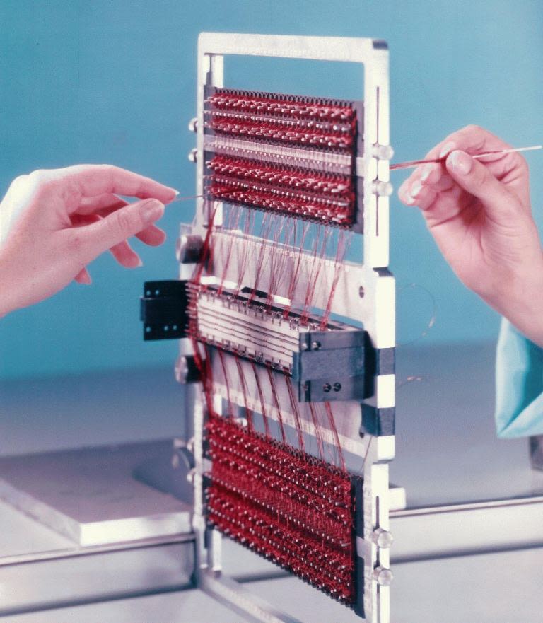
Hands weaving Core Rope Memory


Man on the Moon
Apollo 11 was the fulfilment of a mandate dreamt in the early 1960s during the Eisenhower administration, reinforced by John F. Kennedy with his 1961 commitment of the USA to “Landing man on the moon and returning him safely to the earth” and made reality by a cross organizational team of Weavers, Engineers, Programmers, Librarians, Clerks, Draftspeople. Some of whom are the subject of this body of research.
Each Apollo mission before Apollo 11, was by no means a failure, but rather one iteration among many of the first successful manned lunar expedition. Iterations and tests are Prototypes; complex, low tolerance technical objects and thus the method of problem solving that requires hours of work and commitment to be fulfilled. This method of discovery was crucial to the development of the Apollo Guidance Computer that made the Apollo 11 mission possible and it’s memory hardware without which 1968 would have stayed as a long shot for landing man on the moon and returning him safely to earth.
As a parallel to the aspirational achievement of the lunar expedition, the prototypical nature of the work meant that the field of Software engineering, computer memory storage and speed of processing advanced beyond anticipated levels.
Left:
E (IM) - 4(1). 1969, 2018
Launch of the Saturn V Rocket on July 16 1969 for the Apollo 11 Mission

A Winding Path
The first question was: how do we land on the moon? The Apollo 11 mission profile was an iterative one, that cascaded into the iterative nature of the computer and memory design.
Planners rejected the idea of a direct flight path as its requirements were out of the capacity of technology at the time. The solution? The Apollo 11 was to have a separate lander that would segment the guidance problem into manageable chunks.
(1-5)
The entire spacecraft will first be placed in earths orbit for one or 2 revolutions
(6-9)
As it arrived near the moon would enter a lunar orbit
(10-17)
The Lunar Excursion module would detach from the Command Module and descend to the moon’s surface
(18-21)
A part of the lander would return to the spacecraft still in orbit and transfer crew and surface samples
This necessitated 2 computers that would both form the Primary Guidance Navigation and Control System (PGNCS) : The Command Module (CM) and the Lunar Ejection Module (LEM). The implication was that the the production requirements of the teams involved were doubled.
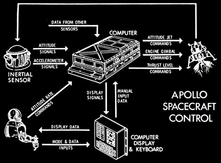
Left:
P (IM) - 2(1). 1969
Overall Apollo Mission. The Guidance, Navigation and Control of a manned Lunar Landing.

In 1961, NASA officially contracted the MIT instrumentation Lab for the design, Development and construction of the Apollo Guidance and Navigation system, including software.
The Apollo Lunar Landing program was a unique challenge to NASA and quite frankly anyone who heard of it. The dilemma of navigating from earth to the moon meant that the spacecraft designed for this purpose would have a certain level of autonomy determined by a computer to assist in its navigation, guidance and flight control problems.
The instrumentation Lab at MIT, now Draper had prior work in small computers for aerospace use as early as the 1950s. Figures like Dr Raymond Alonso and Eldon Hall had designed devices with applications in the industry. In 1961, Robert G Chilton (NASA) and Milton Tragesar (MIT) setup the basic configuration for the Apollo Guidance System and to the surprise of a few, an on board digital computer was included. Not just any digital computer, but a navigation and guidance computer with inertial and optical sensors.
The justification for this was the need to avoid hostile jamming, a preference for longer duration manned missions and to prevent saturation of ground stations in the event of multiple missions in space simultaneously.
Opposite:
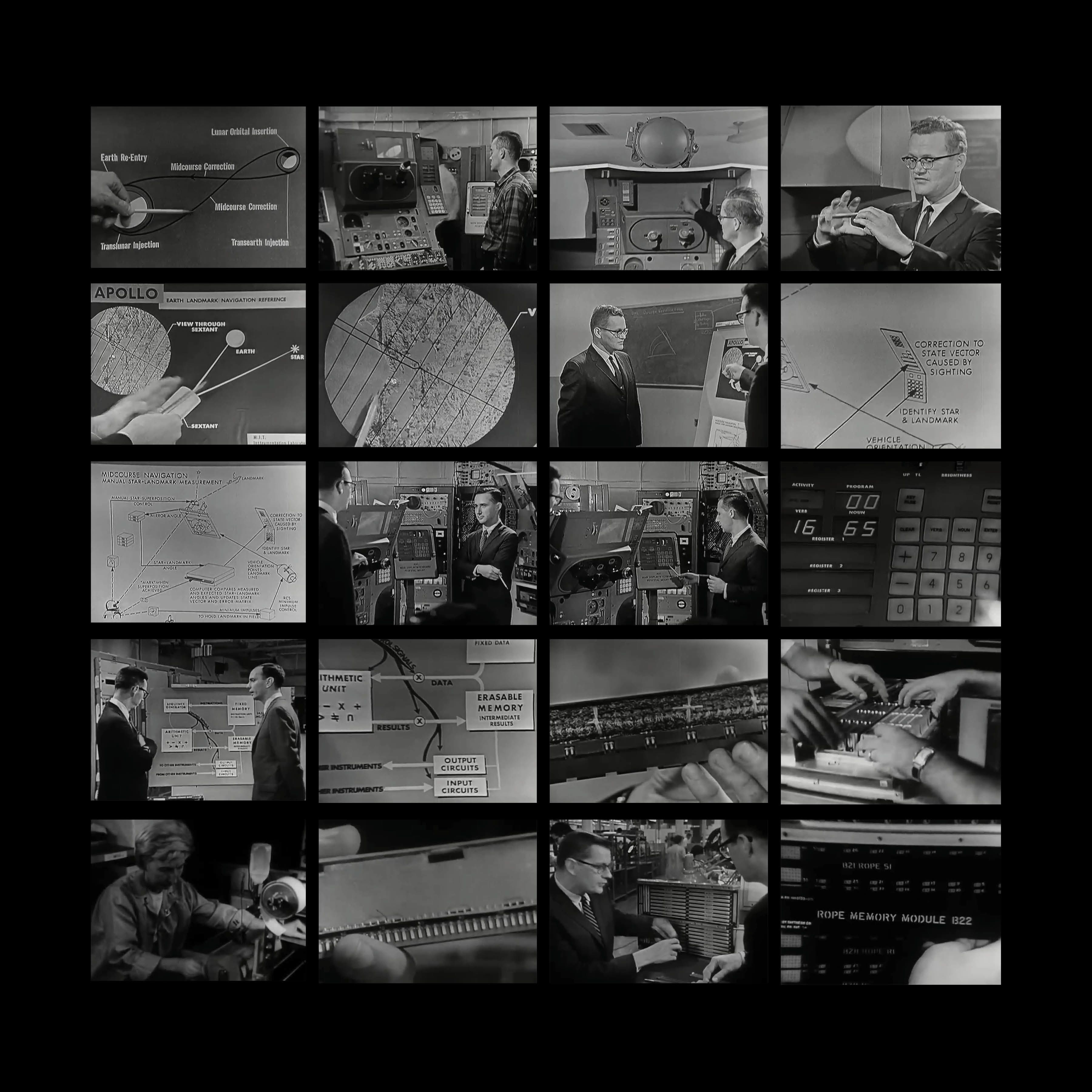
F-2, 1965
Scientists and engineers Eldon Hall, Ramon Alonzo and Albert Hopkins (of the MIT Instrumentation Laboratory) and Jack Poundstone (Raytheon Space Division in Waltham MA) explain and demonstrate key features of the instruments, and detail project challenges such as controlling the trajectory of the spacecraft, the operation of the onboard telescope, and the computer construction and its memory. The program was presented by MIT in association with WGBH-TV Boston, and hosted by MIT reporter John Fitch; it was produced for NASA. Source

The Fourth Crew Member
Neil, Buzz, Michael and the AGC
What started off as a vision for an autonomous space flight, ended up as a symbiotic relationship with the on ground crew. The ground computers determined the vehicle’s position in 3-d space, performing the necessary calculations that eventually got transmitted to the computer on board the spacecraft.
Autonomy in the end was that the spacecraft could return safely to earth without help from the ground. The AGC was called the fourth crew member because of its fully integrated into the spacecraft as well as its capabilities.
Left:
E(IM) - 8(1), 1960s
The Apollo LM primary guidance and navigation system

The astronaut would play a role in operating the spacecraft as opposed to being a passive passenger.
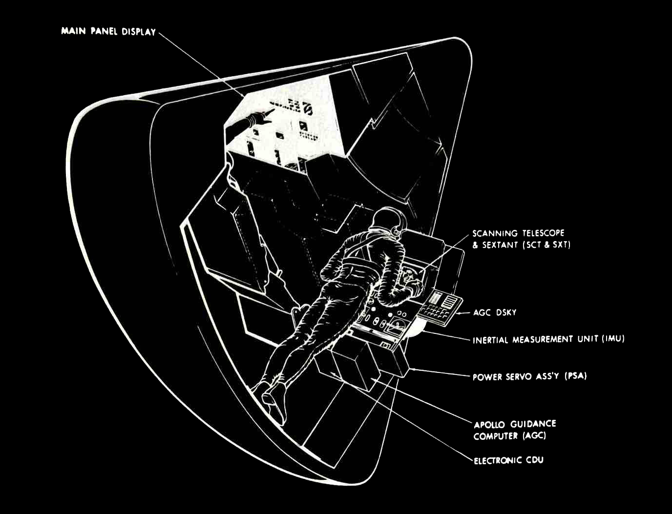
Crew members could communicate with the Computer using a display and keyboard unit (DSKY, pronounced Discky). There were 2 DSKY’s in the Command Module, one in the main control panel and one near the optical instruments at the navigator’s station.
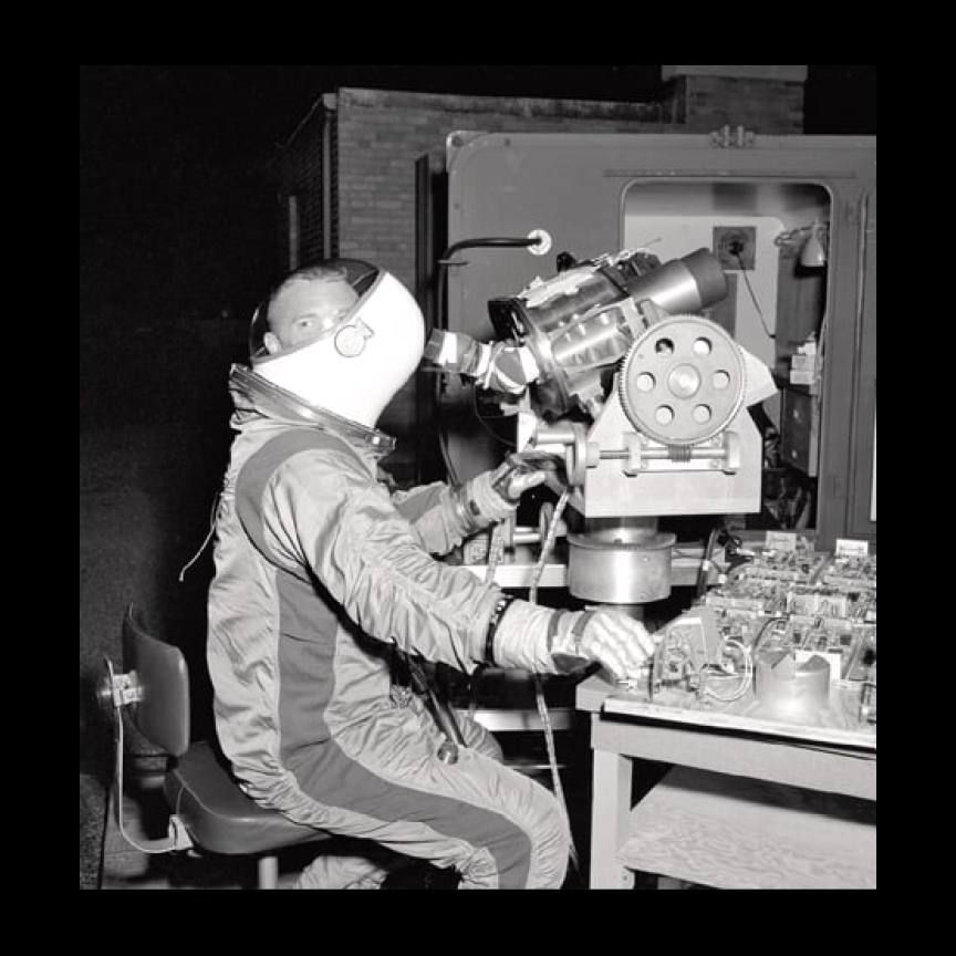
Left:
B(IM) - 1(3), 1960s. 2019
Astronaut Rusty Schweickart goofing off, with his helmet backwards, while testing the optics for the Apollo Guidance Computer at MIT.
Top:
P(IM) - 2(2), 1969
Location of the Guidance and Navigation System in the Command Module

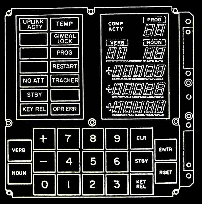
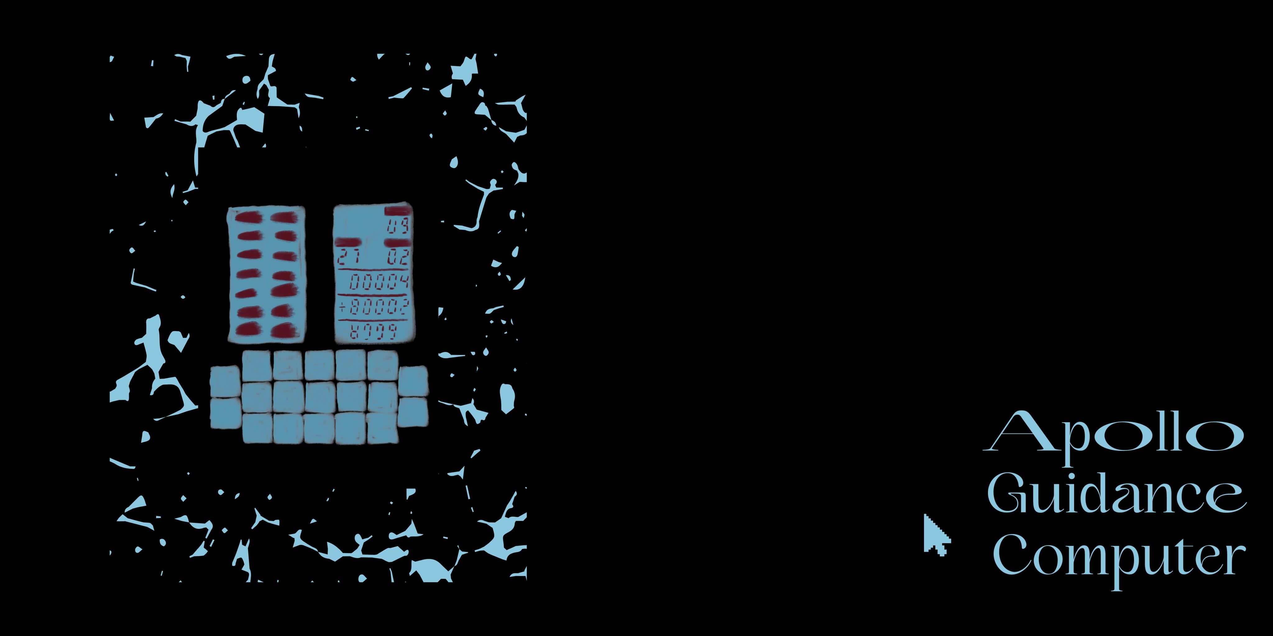
DSKY
The computer could communicate with the crew through PROGram, VERBB and NOUN displays.
PROG: This was a two-digit display indicating what numbered program the computer was currently executing.
VERB: An action to be performed e.g Display
NOUN: The object of the action e.g. Time to Ignition
Verb 37, for example, was “Change Prog,” which enabled the crew to set up a new program for execution.
In the end, it took 10,500 strokes to complete the lunar mission. This simplified user interface, as a way to read and temporarily write on the AGC, formed the basis for the prototyping carried out in the later part of this project.
Left:
B(IM) - 1(3), 1960s. 2019
Astronaut Rusty Schweickart goofing off, with his helmet backwards, while testing the optics for the Apollo Guidance Computer at MIT.
Top:
P(IM) - 2(2), 1969
Location of the Guidance and Navigation System in the Command Module
Integrated circuits
The spacecraft that was dreamed of in 1961 differed significantly to what flew to the moon in 1969. At the time, It was MIT’s most ambitious attempt at an embedded computer system. During the process of iterating the AGC, there was a transition from Block I to what was known as Block II. Block I was based on prior technology that had been developed at the institution similar to the Polaris System Technology.
Block II was a more advanced design that was suitable for the combined CM-LEM mission path. With Block II, MIT was spurred to develop Integrated Circuits to replace core transistor circuits. The Block II took up less space and had faster processing times. The incorporation of integrated circuits spurred the development of silicon chips as we know them today. Only a 3 year old technology in 1962, 80% of the integrated circuits that were produced on the West Coast, went to the Apollo Mission.
Block II measured 24 x 12.5 x 6 inches, weighed 70.1 pounds and required 70 watts at 28 volts DC.
Left:
E (IM) - 28(1). 1962, 2019
The AGC-4, an engineering model of the Apollo Guidance Computer from 1962 and the first to include Integrated Circuits.
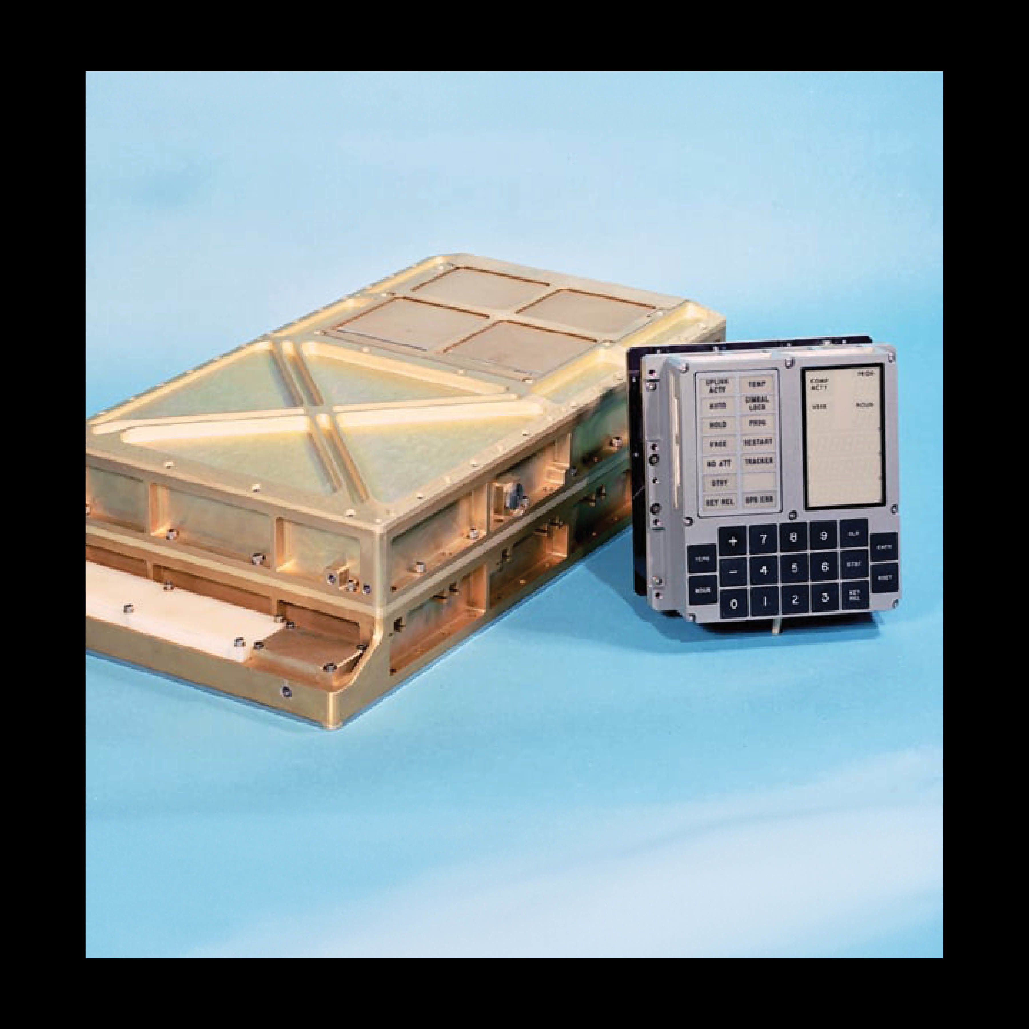

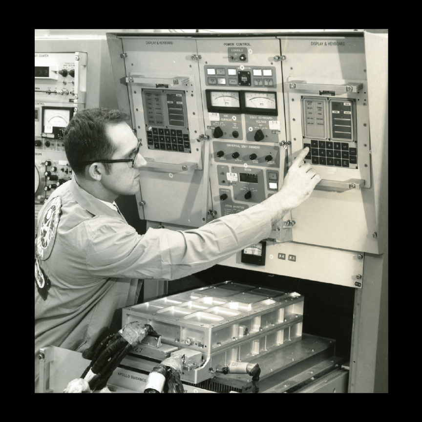
Left:
B(IM) - 1(1), 1960s, 2019
Block II Apollo Guidance Computer Component with DSKY (display and keyboard)
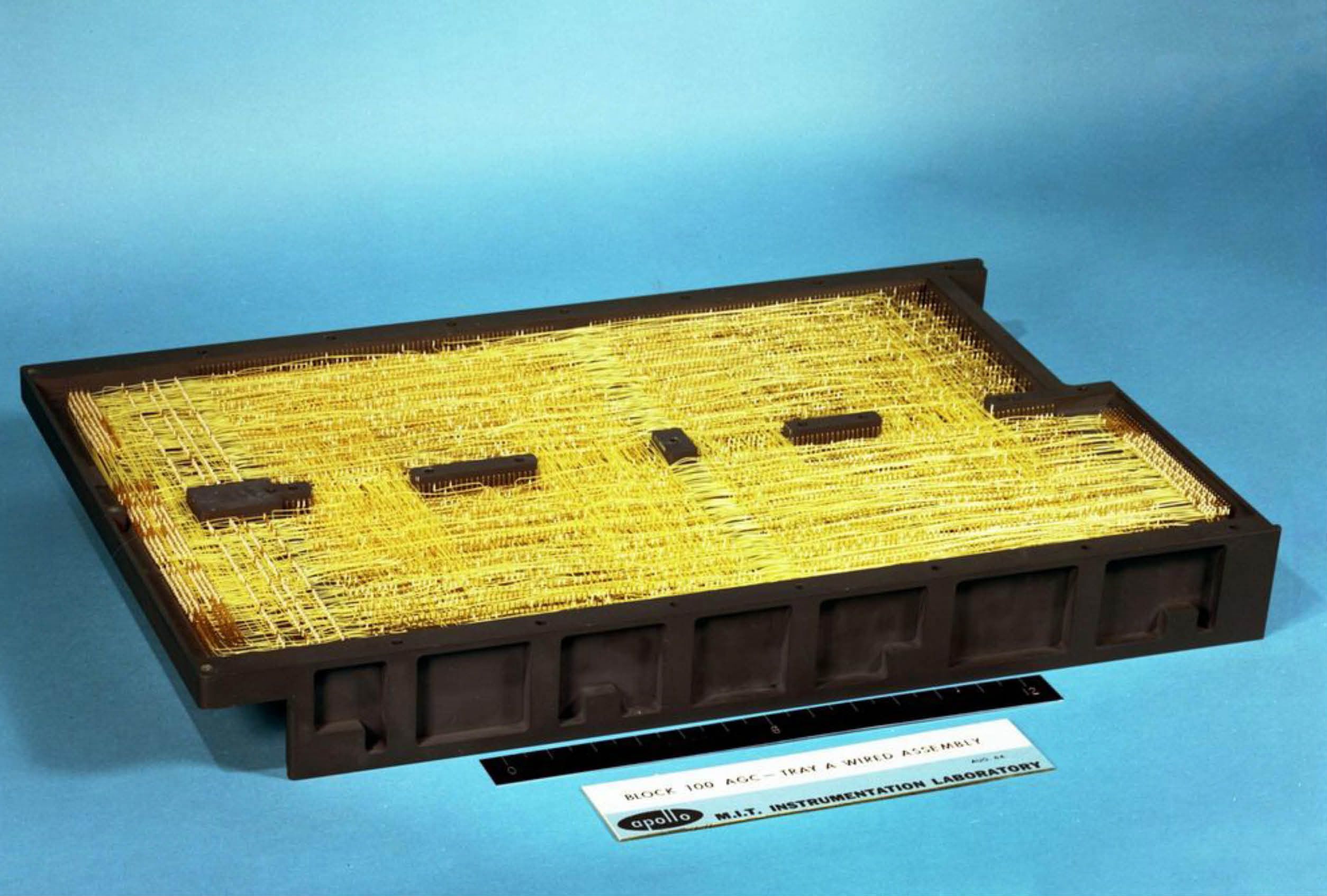
Top:
E(IM) - 15(1), 2020
A Fully wired tray A of the Apollo Guidance Computer
Light, Efficient,
Complex yet compact,
Secure and indestructible
The requirements of memory were the most difficult to determine in the process of designing the Apollo 11 spacecraft. Apollo’s computer had two forms of memory, fixed and erasable, similar to today’s terms of Read only Memory (ROM) and Random Access Memory (RAM).
It used erasable memory cells to store calculation results and real time data such as the location of the spacecraft, as references for other logic operations.
It used fixed memory cells to store programs that did not need to be changed during the course of a mission.
With a start of 4k words of fixed memory and 256 words of erasable memory, the final design eventually had:
- 2,048-word erasable memory
- 36,864 -word fixed memory
The Arrays were wired on 32 x 64 planes folded to fit into a 9-cubic-inch module. The AGC had 2 trays of memory with 24 modules. Each module had 2 groups of 60 flat packs with 72-pin connectors all hermetically sealed.
The memory was divided into banks of core and the addressing was done by first indicating the bank required and then an address within the bank. The lightness of this design was only made possible by the form of memory deployed, magnetic core memory.
The aim of engineers was to combine what humans do best with what machines do best in order to create a system that offers high efficiency and operational flexibility in missions. Magnetic Core Memory was thus a combination of efficient computation capabilities with the capacity for large amounts of complex information, in a densely packed wire configuration that could only be done by weaving. The ferrite cores the sense wires were woven in and around could fit on the wings of a housefly.
It marked the shift from big to small packages as an earmark for computer complexity.
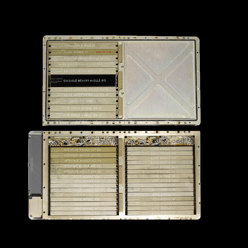
Left:
E (IM) - 27(1), U
Fully Assembled Trays of the AGC showing the fixed memory and writable memory
First Came Whirlwind I
For both NASA, MIT and the subcontractors involved, it was a learning process. The relevant technology was developing simultaneously as the Apollo projects were taking shape.
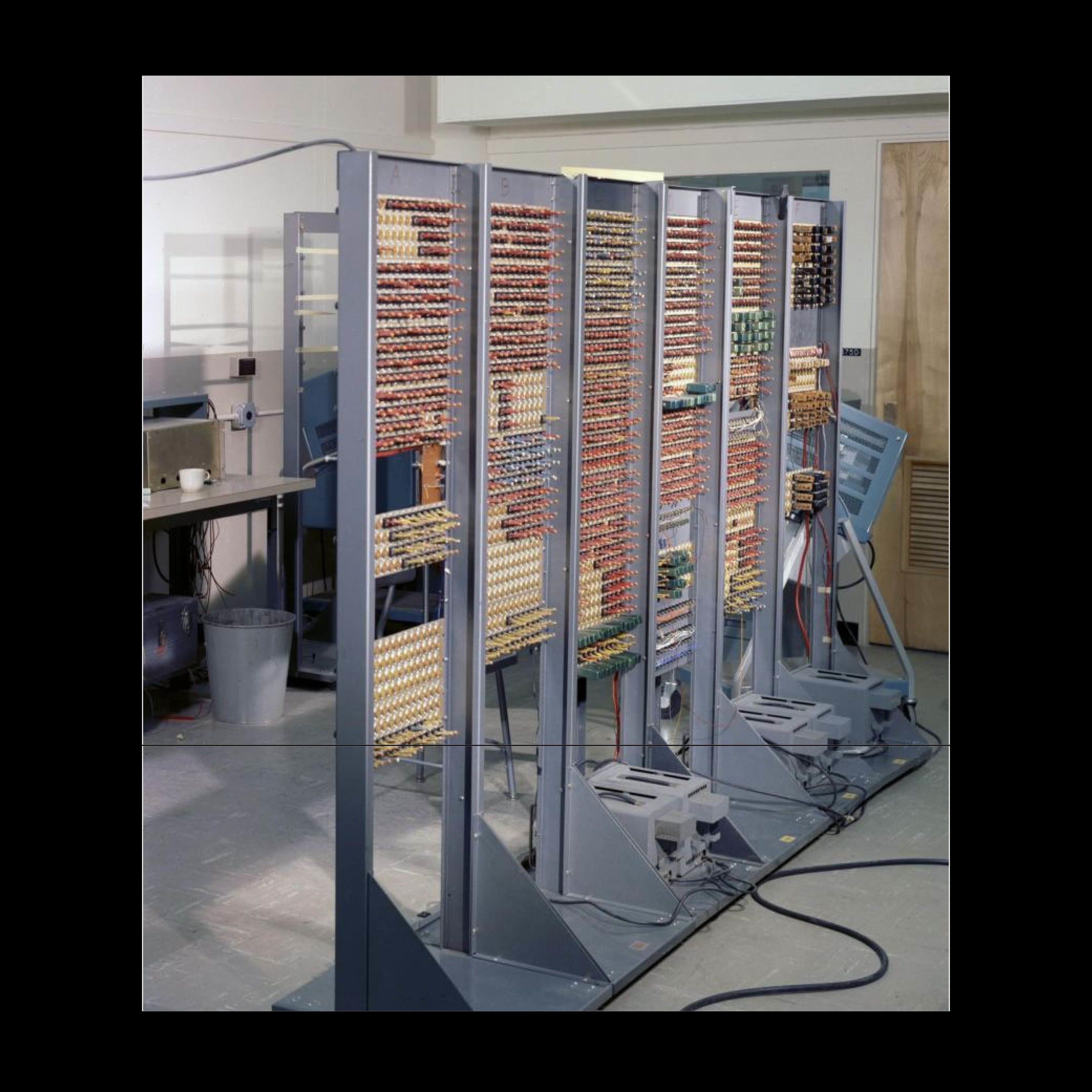
Before the AGC, stored-program digital computers could occupy whole rooms with ENIAC (1943) at Upenn and Whirlwind(1951) at MIT as crucial examples. The Apollo Guidance Computer however, was a 24 x 12.5 x 6 inch computer weighing 70.1 pounds with compact woven storage and a memory capacity of 72 Kilobytes. Infinitessimal numbers when you consider a 4.5” x 2.4” x 0.46” device weighing 4.76 pounds today, can have a storage of 72Gigabytes , a million times more storage than the spacecraft that took man to the moon.
In 1951, The Whirlwind I was released by MIT , obtaining the record for the fastest computer at the time. It was also the culmination of research into Magnetic Core Memory that was developing at the institute.
Left:
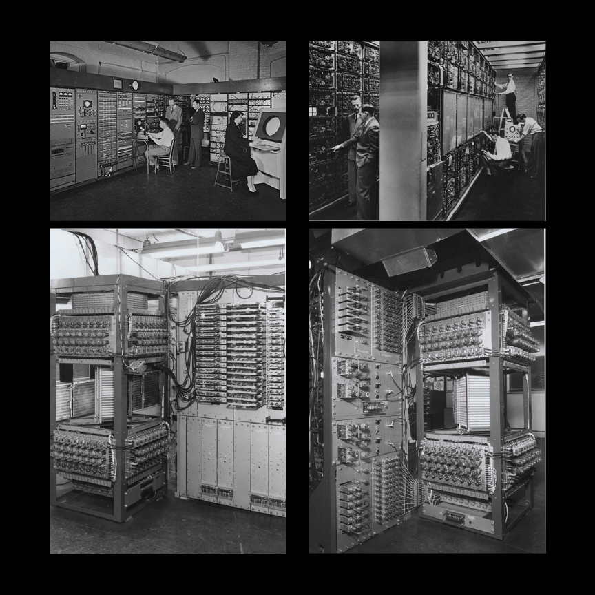
A (IM) - 3(1), 1951
S.H Dodd (In charge of Computer Operation), J W Forrester, Director of the Laboratory, R.R Everett, Associate Director and Ramona Ferenz shown watching the solution of a problem
A (IM) - 3(2), 1951
In the View of the computer, Jay W Forrester, Director of the laboratory and Norman Taylor, Head of Electronic Development examine a section of the arithmetic element of Whirlwind. Right, John a. O’brien, Charles L Cordeman and Norman L Daggett check the operation of one of whirlwind’s 32 Electrostatic memory tubes. The computer is capable of performing 20,000 arithmetic or logical operations per second

Jay W. Forrester was crucial to the development of Magnetic Core Memory. He holds the patent Magnetic Core memory (1949). He was responsible for the design and construction of Whirlwind I and In his computing work, Forrester invented random-access, coincident-current magnetic memory that served as the standard memory device for digital computers through the 60s and into the 70s.
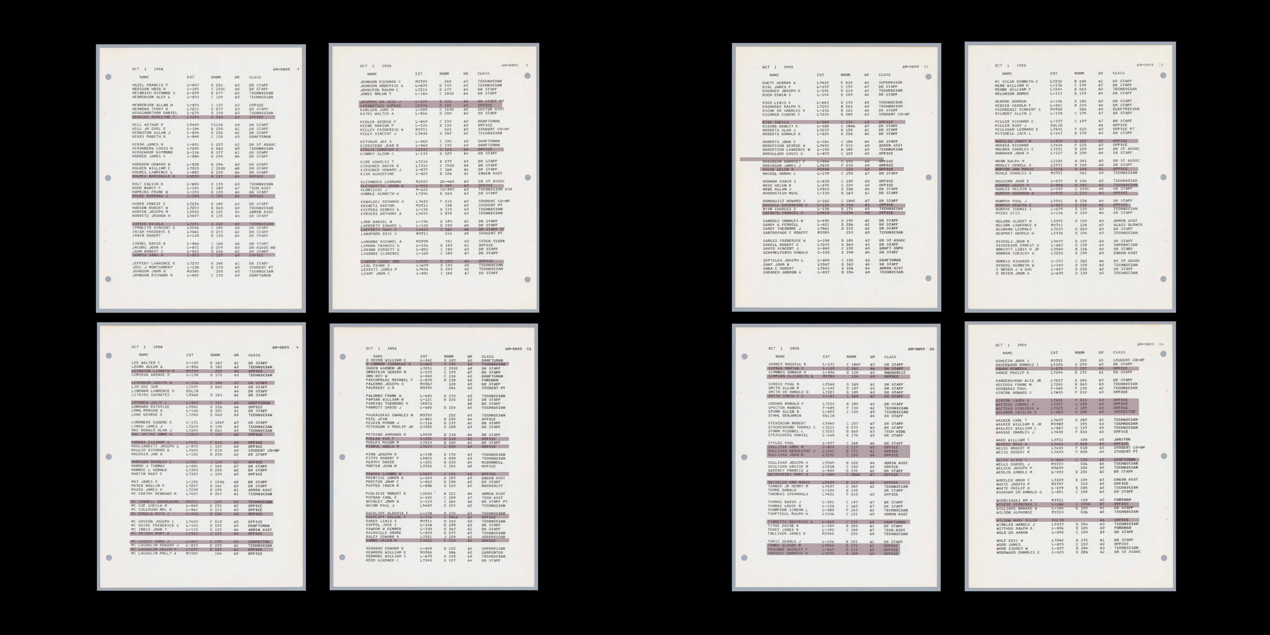
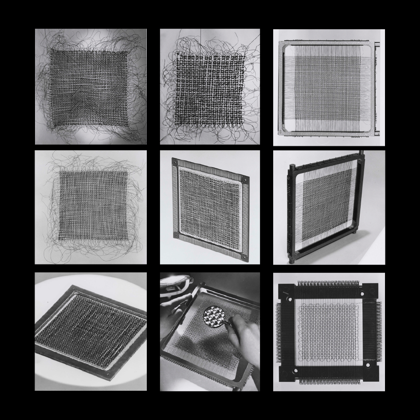
The development of Woven memory was a highly iterative process. A team at MIT was dedicated to testing the magnetic cores of different materials and sizes, wires, temperature that were the right fit for different memory storage applications. Amongst the team were women, whose names we uncovered from personnel logs and documentation of the different iterations.
Left:
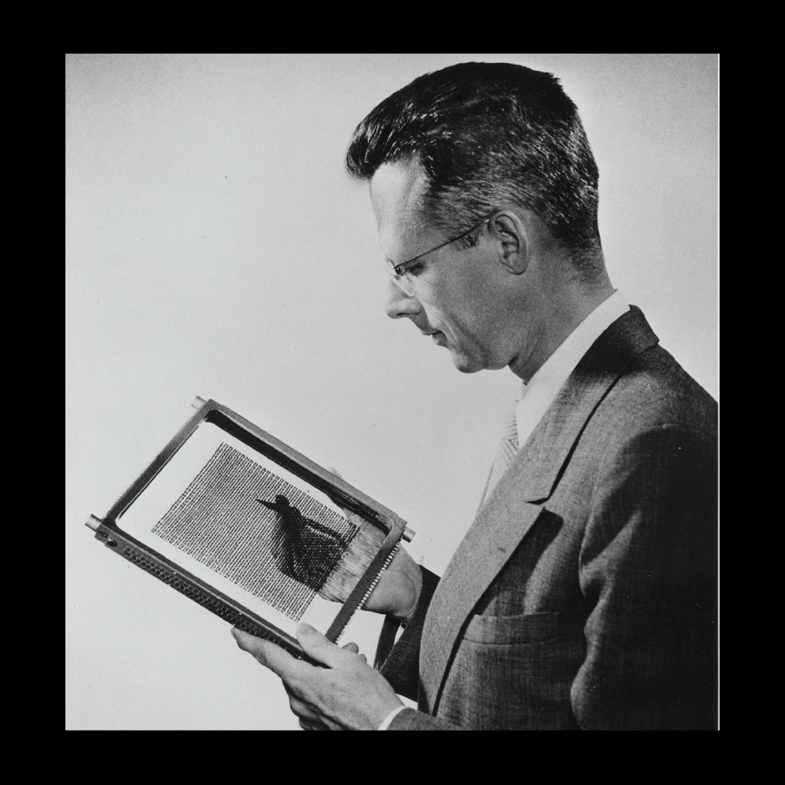
A (IM) - 2(14), 1954-1962, 45276
Jay W. Forrester holding MTC 64 x 64 Digit Plane
Top:
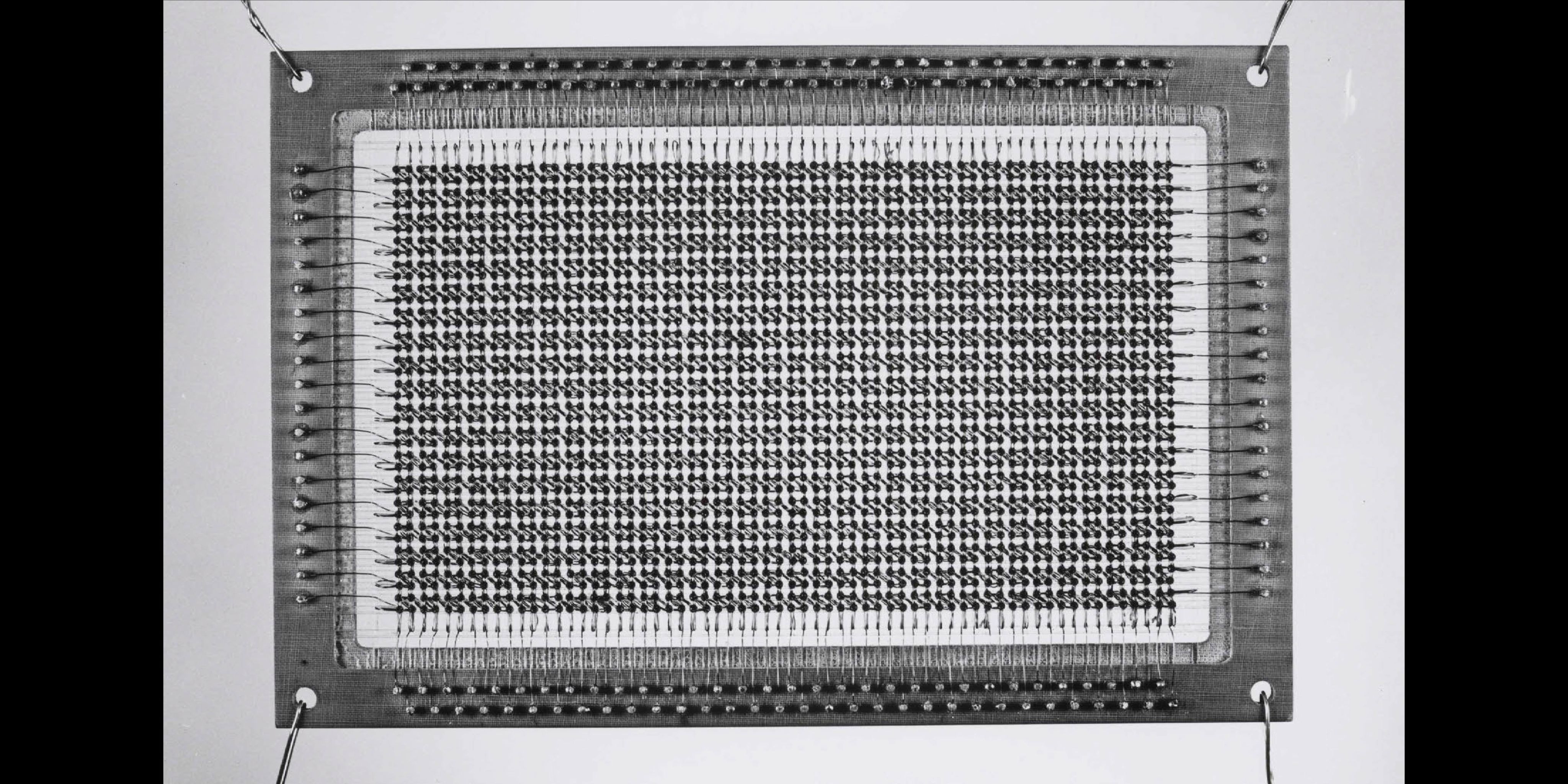
A (IM) - 2(15), 1954-1962, 45276
64 Ferrite Memory Plane

Software as hardware
Core Rope memory was Electromechanical memory. It could not be lost. if you had an electrical failure, it could still work. It could only be damaged physically. It was software woven as hardware.
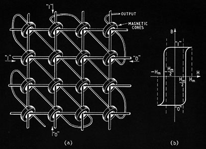
Memory was stored as binary, 1’s and 0’s. If a 1 was recorded, it went through the ferrite core. If a 0 was recorded, the wire went around it. For one memory component, it took bundles of a half mile of wire woven through 512 cores. One module could store more than 65,000 pieces of information.
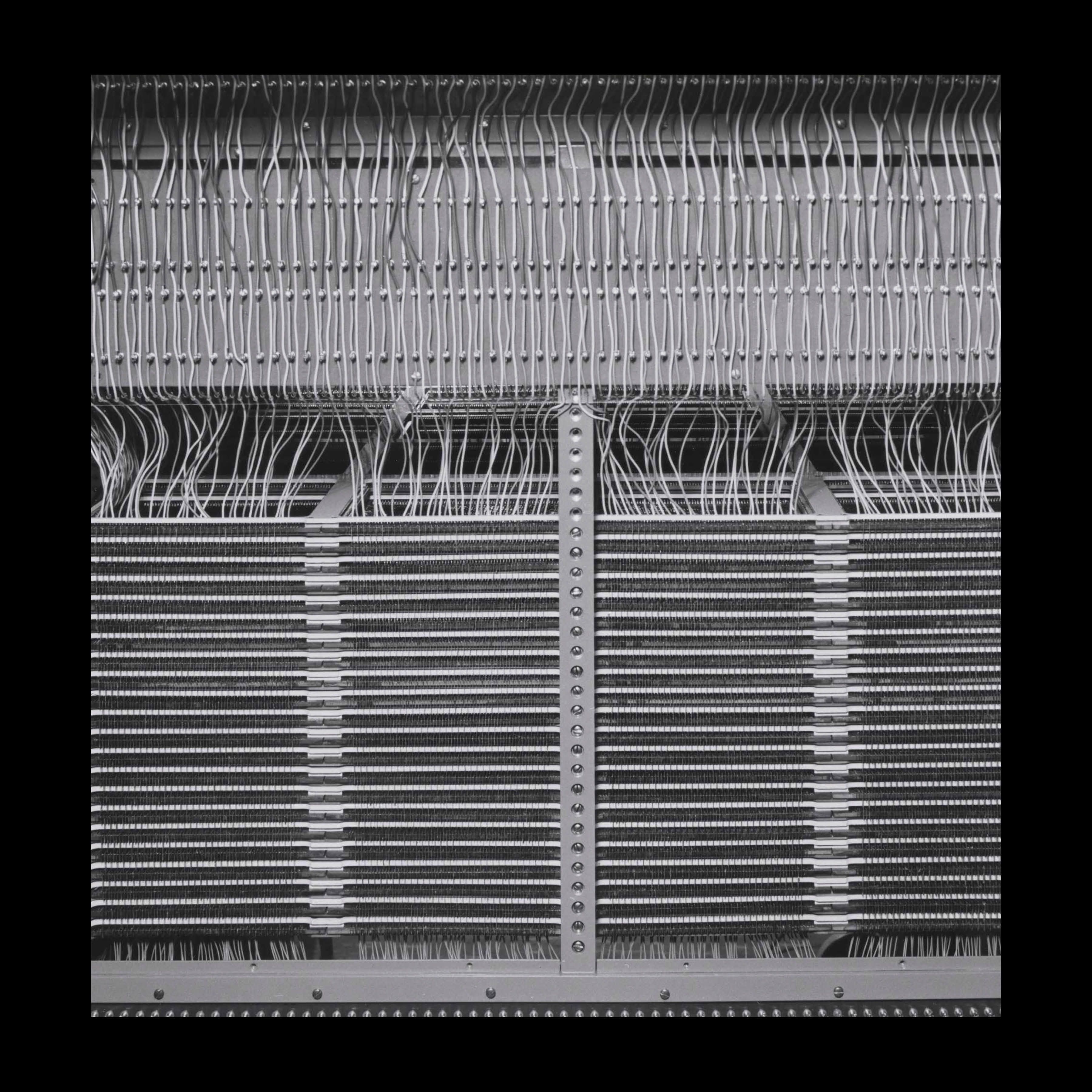
By 1965, a more mechanical method of weaving the wires was implemented, based on machines used in New England’s textile industry. But still the process was extremely tedious, and one program could take several weeks or even months to weave, with more time needed to test it. Any errors in the weaving meant it had to be redone. The Command Module computer contained six sets of core-rope modules, while the Lunar Module computer held seven.
Opposite, Clockwise from left:
A (IM) - 2(M), 1954-1962, 45276
Core Memory Planes from DDC Core Rope Memory Archives
Top:
E (IM) - 9(7), 2023
Core rope memory works by magnetizing small rings with an electric current. Source: T.E. Ival

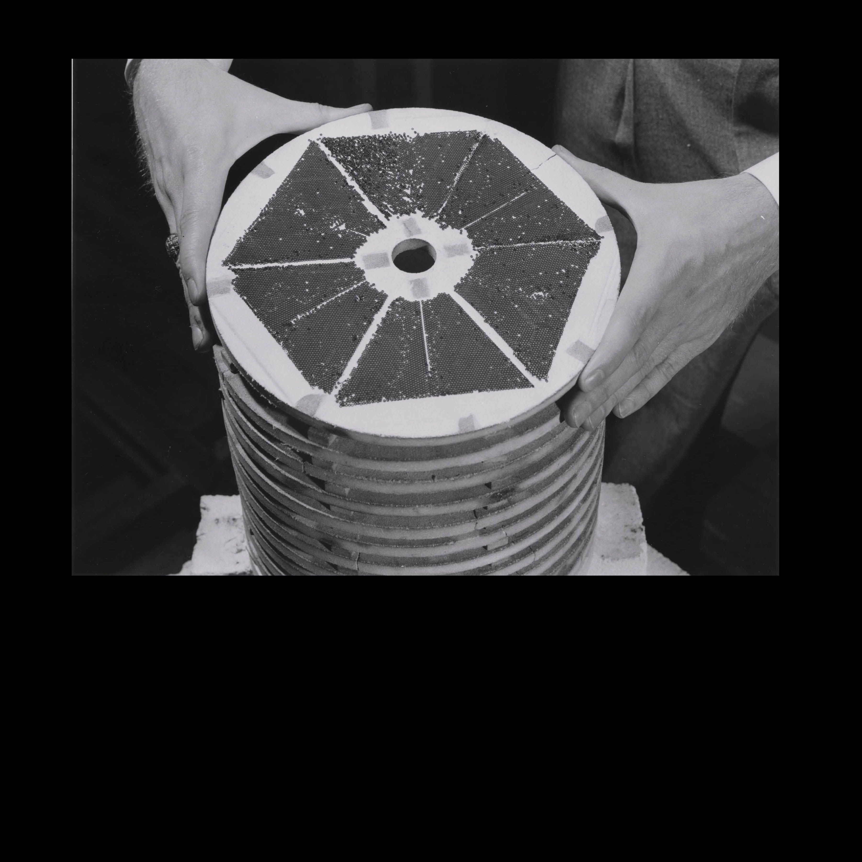
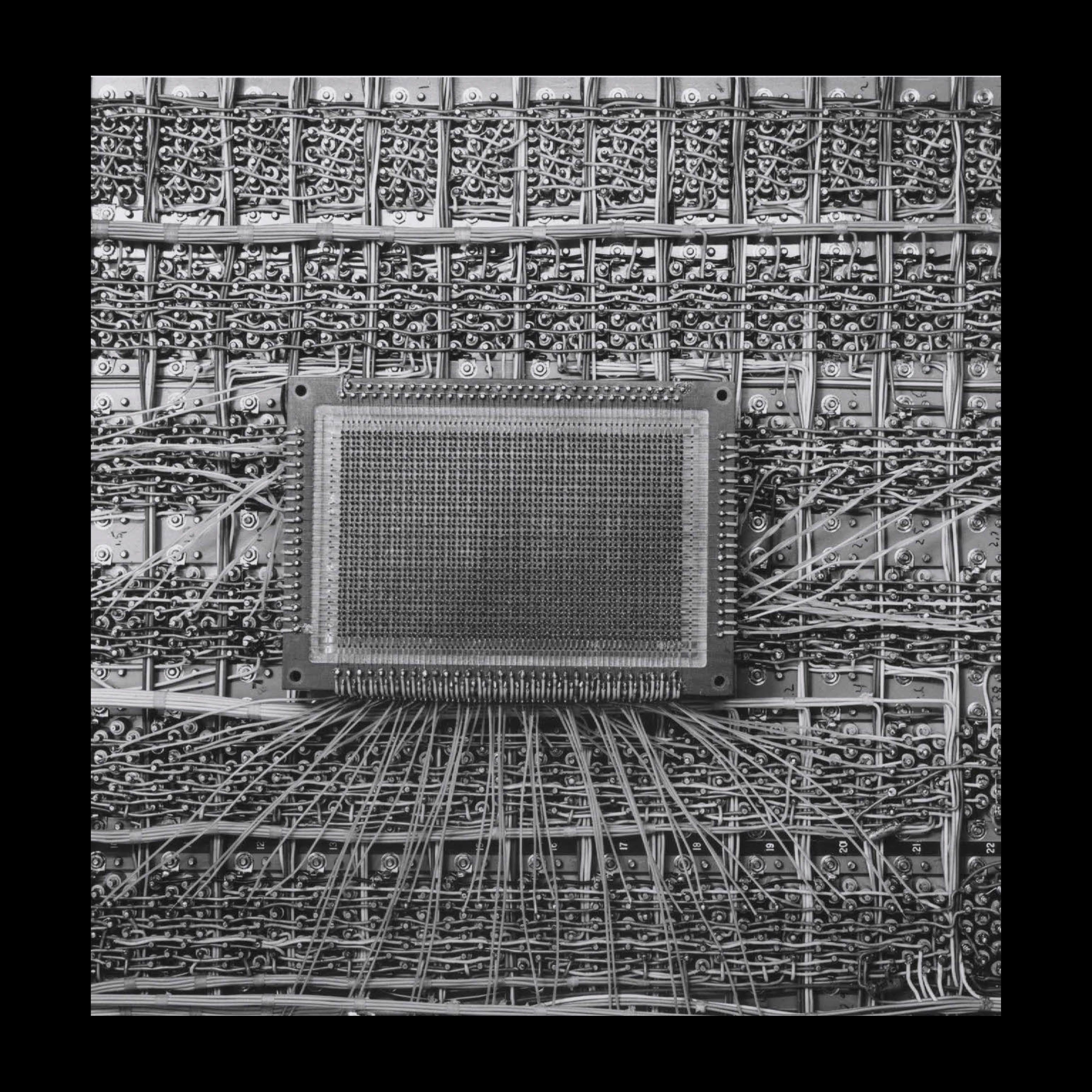
Left:
A (IM) - 2(18), 1954-1962, 45276
59 Ferrrite Memory Bank
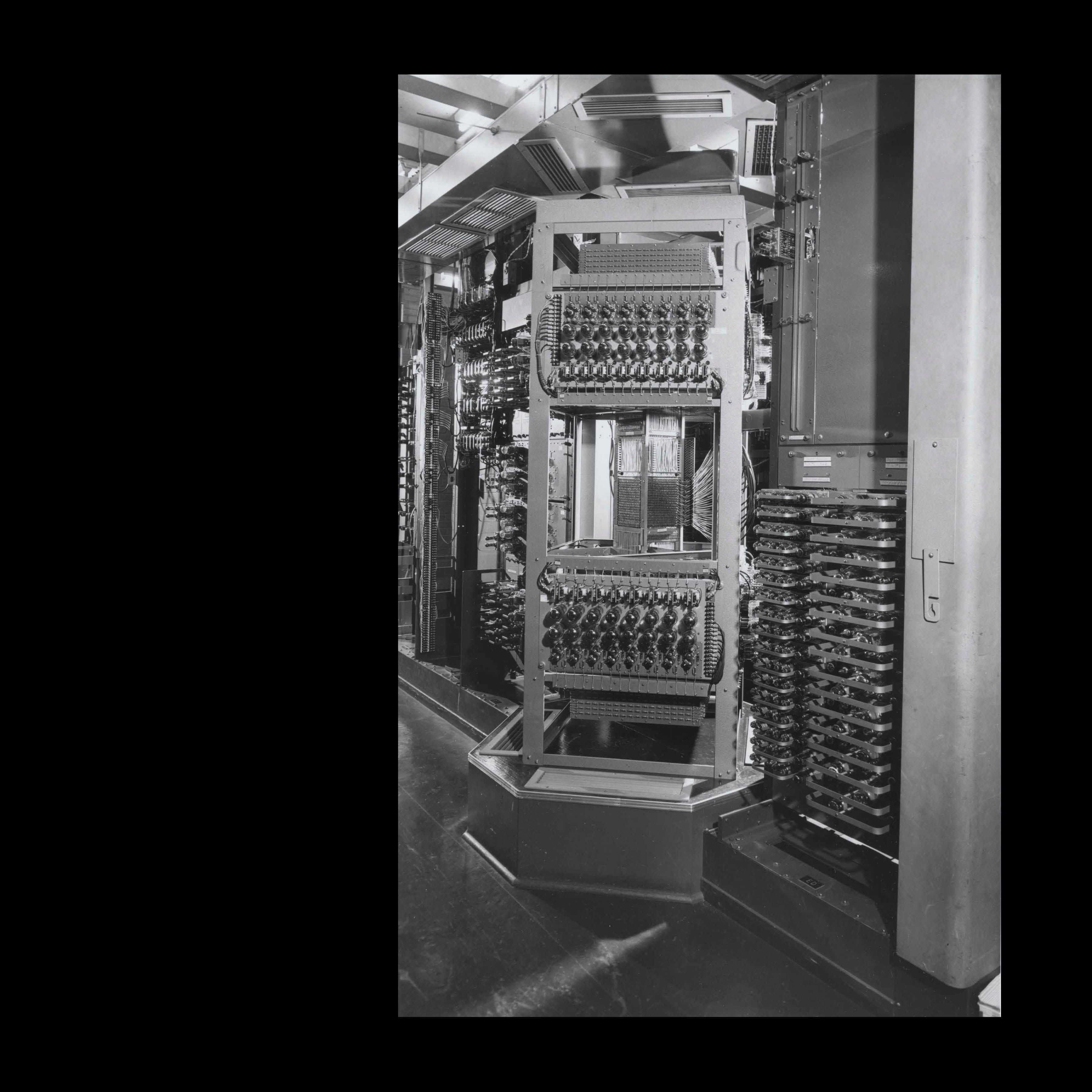
Top:
A (IM) - 2(19), 1954-1962, 45276
60 Harper Furnace
Left:
A (IM) - 2(20), 1954-1962, 45276
Computer TX-2,162 Memory